There are many types of LED displays, and different types of displays have different uses. Each method has its own advantages and disadvantages. At present, LED displays have breakthroughs in color and size, and can achieve full-color coverage with a size of hundreds of square meters.
1. Classification of LED display types
1.1 Classification by usage environment
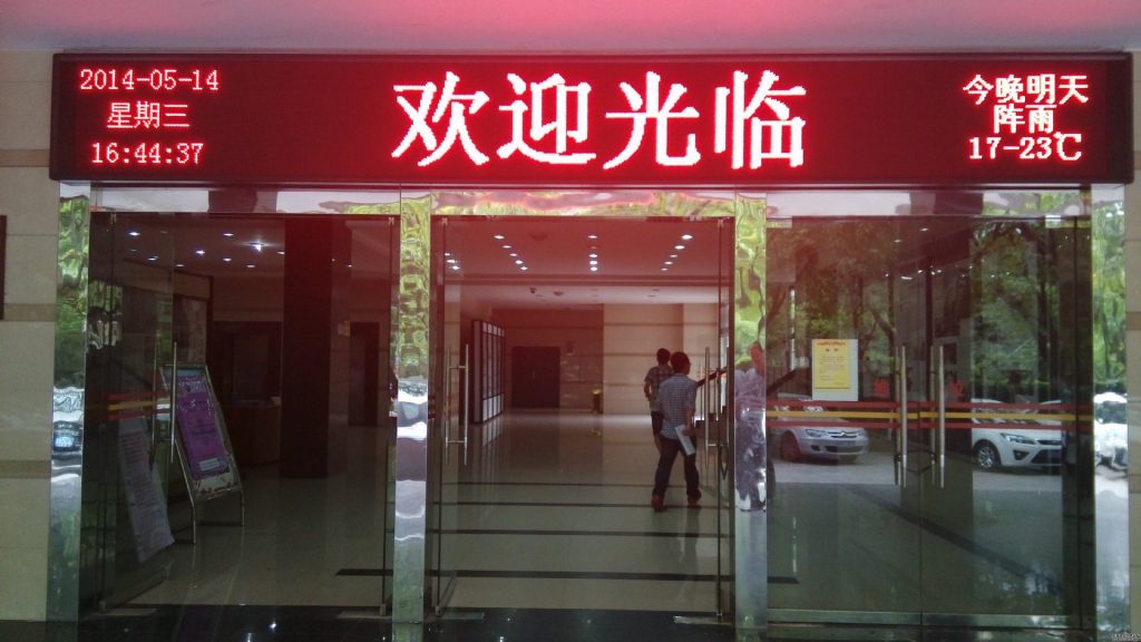
According to the use environment, it can be divided into indoor LED display and outdoor LED display. Indoor LED display is characterized by large viewing angle, moderate screen brightness, high density, light weight, suitable for close viewing; outdoor LED display is characterized by long color mixing time, high screen brightness, waterproof and anti-ultraviolet.
1.2 Classification by display function
According to the display mode, a function can be divided into graphic LED display, video LED display and digital display. The function of the graphic LED display screen, as the name suggests, is to display pictures, text information, online and offline display; the video LED display function can display real-time, video, video and other 2D or 3D video information; digital display equipment It is a 7-segment digital tube, Mainly used to display digital electronic screens, electronic clocks and so on.
1.3 Classification by display color
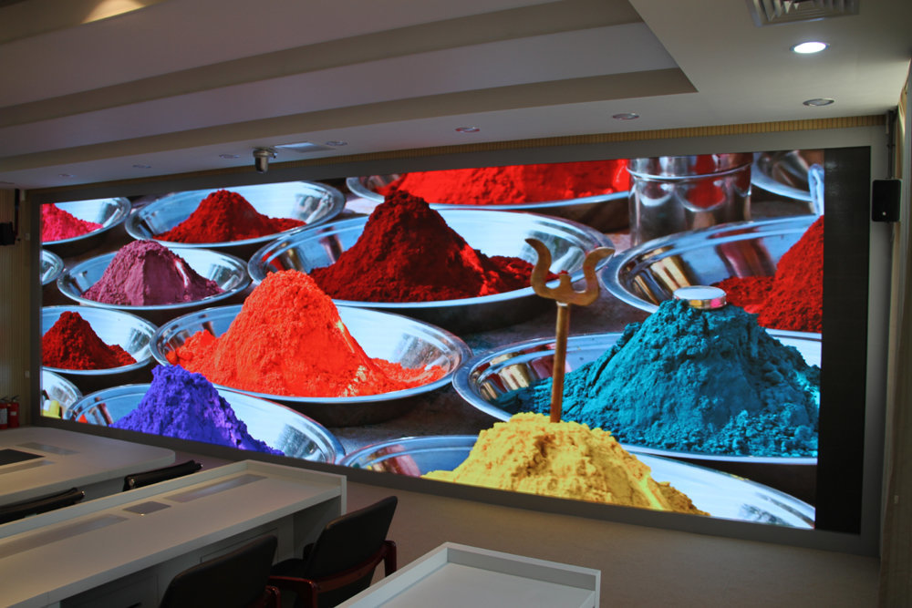
According to the display mode, the color can be divided into single-color display, double-color display, full-color display. The single-color LED display is composed of single-color LEDs and can only display one color; the two-color LED display is composed of red and green LED lights; the 256-level two-color LED display can display 65,536 colors; the full-color display is composed of red and green LEDs. , green, blue three-color LED composition, 256-level full-color LED display up to 16777216 colors.
1.4 Classification by Display
Press display can be divided into page display, horizontal scrolling, static and vertical scrolling.
1.5 Classification by Control Mode
According to the control mode, it can be divided into synchronous mode and asynchronous mode. The synchronous display mode is equivalent to the LED display as the monitor of the computer, and the multi-gray display capability is realized by mapping the mapped computer image on the monitor; the asynchronous display mode utilizes the storage function and automatic playback function of the LED display. On the computer, the edited text and pictures will be transferred to the LED display, and the LED display will play automatically. This method is often used to display textual information because it lacks the ability to display multiple levels of grayscale.
2. LED display design
2.1 LED display design principles
The principles that LED displays should consider include: reliability, compatibility, practicability, cost-effectiveness, etc. In terms of reliability, the effect that needs to be achieved is that the software and hardware of the entire system can run stably to ensure that no defects are displayed on the daily information display screen, and the progress is smooth; compatibility mainly means that the system can normally access the computer and various video signals. Normal display of network content; practicability mainly refers to being suitable for various conditions and meeting the requirements of graphic information, video, and official document display information.
2.2 LED display design
2.2.1 Design of Display Drive Circuit
The display driver circuit is generally located behind the display screen as a PUB board. The display drive circuit controls the information that needs to be displayed, and can display the display screen according to certain timing and rules; and provides the corresponding driving current and level for the light-emitting diodes on the circuit board, so that the display screen can display data, patterns, and videos as needed. Wait. text and other content.
The design idea of the display driving circuit is to use “line lighting, column scanning”, that is, placing light-emitting diodes on the dot matrix module where the column lines and the row lines intersect. The connection mode between modules is determined by the scan mode. Scanning modes are divided into 1/16, 1/8, 1/4, 1/2, 1/1 and so on. The meaning of 1/16 is to refresh one row at a time, one scan period is 16, and the control signal needs four ABCD; 1/8 is to refresh one row at a time, one scan period is 8, and the control signal needs ABC; analogy can get 1/4, 1/2, 1/1 scan period and control signal. The 1/16 scan brightness is higher than 1/8, so the scan is generally 1/4 under strong light, and the 1/16 scan is generally used indoors.
Selecting the driver circuit chip is also a very important task. Driver circuit chips can generally be divided into amplifying chips, decoding chips, line driver tubes, LED driver chips, etc. The principle of selecting a power amplifier chip is to increase the power of the control signal and amplify the power due to too many cascaded display modules.
The general choice is 74HC245; the principle of choosing the decoding chip is: serial transmission is required. Signal decoding, so that the optical signal is transmitted to the display template, generally choose 74HC138; the principle of selecting the driving tube is to choose the high-current action driving of the display line. It is generally 4953; the principle of selecting an LED driver chip is to select a suitable LED driver chip to provide sufficient current and matching level for the LED. The model number is usually 74HC595 8-bit, A6282 16-bit, or TB62726.
The PCB design principle is to install matching solder holes on the front side of the PCB. It is a combination of PCB and display
2.2.2 Design of Display Panel
The display panel relies on many independent dot matrix display modules and is further spliced. Each dot matrix display module consists of multiple light-emitting points. In a monochrome dot matrix display module, each light-emitting point generally corresponds to a light-emitting diode; in a color dot-matrix display module, each light-emitting point has a more complex composition, which can be composed of light-emitting diodes of different colors. After different light-emitting diodes are lit, the light-emitting points will appear different. The color of light is pixels, and the higher the pixels, the more pixels the display panel has, and the higher the display resolution.
In the room, the display screen generally adopts 8*8 display module. Another way is to say that the pixel density is 64 pixels. Outdoors, the dot matrix display module used on the display screen is not fixed, and the materials used are flexible. Generally speaking, it can be customized according to the user’s needs, or you can choose the appropriate brightness and color that the designer needs.
2.2.3 Controlling the computer The core of the display system is the control of the computer. The designer controls the computer and transmits the numbers, images, text, video and other information to be displayed to the display circuit, and can provide control ideas. The control signals sent by the control computer generally include EN enable signal, CLK clock signal, STB latch signal, RI data signal and ABCD line signal.
The EN enable signal can be used to control signals across the screen. It can also blank the display and adjust the appropriate duty cycle by changing the EN enable signal.
The STB latch signal is used to transfer the data in the register to the latch and then display the data through the driver circuit. However, since the driver circuit is controlled by the enable signal, the lighting must be turned on. In state, the latch signal also needs to be coordinated with the clock signal to display a pleasing image;
The RI data signal can provide the required transmission data for the display. It works by coordinating with the clock signal. The data is then transferred to the display point to be displayed. When the data are not equal, the corresponding color display will be abnormal;
The ABCD line signal exists in the dynamic scan phase. ABCD means four binary lines. The ABCD signal has four lines of 16 lines each, the ABC has three lines, eight lines, and so on.
For more information visit our website led-technic.com