The LED display needs to be controlled by an application-specific integrated circuit (ASIC)-based control system. Companies such as Maxin, Agilent and Toshiba are the major manufacturers of LED display control ASICs in the world. In addition to the development of LED display control technology itself, due to the continuous progress of network technology and the needs of practical applications, the current network-based and intelligent LED control technology also has a new development momentum.
Displays present new challenges. Since LED display technology and network technology are originally independent of each other, to realize network control of LED display, it is necessary to develop relevant terms that comply with network system protocols and specifications.
1. Agilent’s LED display control solution
Agilent is not only an important manufacturer of LEDs, but also one of the world leaders in LED applications. The company has launched three series of outdoor full-color LED screens and two series of indoor full-color LED screens, which are the most complete series of LED displays in the world market. The LED display technology solutions provided by Aailent are as follows:
(1) Data transmission of LED display system
In terms of transmission, large-screen systems generally use serial mode for video data transmission, and optical fiber mode is usually used for reliable transmission over long distances. |
Agilent’s high-speed serializer/deserializer chipset can meet customer requirements for speed and synchronization. Agilent’s HDMP-1032/1034 and HDMP-1 022/1 024 two sets of GLINK chipsets can respectively achieve serial 1 200mbit/s and 1 500Mbit/s fit transfer rates. The parallel port of the chipset is a parallel 16-22-bit TTL level, with a maximum speed of 70MHz I-0 75MHz, while the serial port adopts a high-speed PECL turtle level.
The chipset has a built-in CDR to ensure clock recovery and synchronization under long-distance conditions, making it ideal for long-distance transmission. Users can send 24-bit RGB signals and control signals to the GLINK chipset in two clock cycles, which reduces the demand for the number of bus bits and the number of chipsets, which can effectively reduce costs. The chipset supports command transmission, and the same serial channel can be used to transmit control commands, which can be easily interpreted by the receiver.
The chipset also supports additional parity bit transfers. In short distances, users can use a coaxial cable to connect; in long distances, users can use a pair of optical modules to transmit video signals.
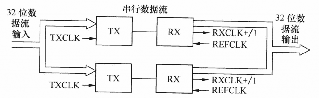
For high-bandwidth applications, such as customers requiring higher color depth, a pair of serializer/deserializer chipsets may not be enough. The GLINK chipset supports two parallel modes, which can be easily upgraded to 2.5GHz bandwidth to Meet customers’ higher bandwidth requirements. The two chip sets are strictly synchronized with the clock, which can simplify the transceiver circuit and logic design, as shown in Figure 1.
In long-distance applications, optical modules are required to ensure reliable transmission, generally optical modules with megahertz sampling. Agilent can provide users with a full range of optical module products, including 100THz, 1 PHz to 10PHz single and multi-mode optical module production crystal. At present, HFBR-53D5 1.25GHz optical module is widely used in the field of large screen.
In general, a pair of GLINK chipsets can meet the user’s requirements, so only one coaxial cable or optical fiber is needed, which greatly simplifies the field wiring and maintenance.
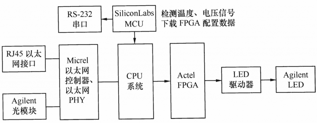
(2)Ethernet interface
In order to support multimedia applications, some large screens are equipped with an Ethernet interface to support the playback of video streams such as MPEG2. As a leading supplier of Ethernet chips, Micrel’s Ethernet products include Ethernet switching chips, Ethernet controllers, Ethernet physical layers and other products, which can meet the Ethernet requirements of large screen systems. These products support l0THz, 100THz Ethernet, with IVDI/MDI¨x JllffE, can automatically adjust the transceiver cable pair, direct or crossover cable can be used.
Micrel’s Ethernet products support cable and fiber optic modes, and fiber optic working mode supports placing the screen at a relatively distant location. The Ethernet controller supports 1-way or 2-way Ethernet, and the CPU supports 8/16/32-bit ISA interface or PCI interface. The Ethernet physical layer chip can provide interfaces such as MII and RMII. The flexible and diverse product line enables customers to choose a more general-purpose CPU to implement their designs.
(3) Out-of-band serial communication
In order to meet the requirements of the large screen to detect the power supply voltage, temperature and other states, some large screen systems use out-of-band serial communication. If the FPGA needs to download and update functions, the data can be downloaded through the microcontroller.
Silicon Labs’ MCU meets these requirements. Its MCU has multiple analog input channels of more than 8 bits, small package, fast speed, and is compatible with traditional 8051; it integrates A/D conversion layer, D/A conversion layer, Flash and RAM; it is a complete soc single-chip microcomputer, which supports the industrial temperature range; at the same time, the single-chip microcomputer supports online upgrades in various ways, and is currently used in large-screen manufacturers.
The role of FPGA in the screen is very important. It is used to complete core functions such as video stream storage and refresh, control and LED. Actel’s third-generation FPGA based on Flash technology has the characteristics of low price, fast speed, built-in boost programming circuit, allowing online upgrades, etc., and it works immediately after power-on, without the process of loading configuration data.
It can support the application of DDR memory. The FPGA has built-in RAM of 18~500kbit and supports LVDS transmission mode. It can be described as a cost-effective FPGA. Actel’s FPGA is very suitable for outdoor environments with severe climate change due to the adoption of Flash technology and excellent radiation resistance.
Shenzhen Shiqiang Guixun Company is an authorized distributor of ARilent, Micrel, SiliconLabs, Actel, which can design suitable electronic display system solutions for customers, and provide integrated circuit applications of display screens, such as synchronous electronic display, synchronization and Asynchronous Ethernet electronic display and other applications.
2. Wireless communication LED display circuit
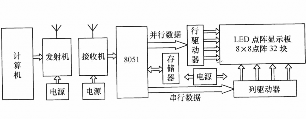
Although the LED display technology is quite mature, its application scope is limited because it often needs to communicate with the computer to display and update information. FIG. 3 is a block diagram of an LED display screen system using wireless communication to update information.
(1) Drive control circuit
The LED drive circuit on the electronic display adopts the serial transmission mode of data, as shown in Figure 4.
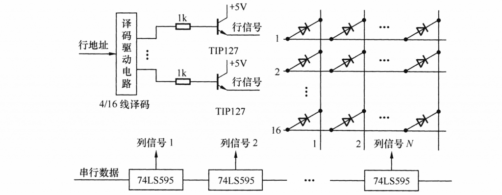
A row address is decoded by a 4/1 6 decoder and then input into an emitter follower. When the output is low, the LED of the row is in a valid state, and an array transfer instruction is used to transfer the data to complete a row. display. That is to say, when the base of a transistor in the 16 rows is at a low level (usually a high level), this transistor is in a state to be turned on.
In the 128 columns, which column is low level, which column’s LED is turned on and emits light, thus completing the display of one column. In order to prevent the 128 points of a certain column from emitting light and causing the drive transistor to burn out due to excessive current, the Darlington device TIP 1 27 with a current of 5A is selected, so that even if the circuit has a static state, the transistor will not be burned out.
The control of the display brightness is realized by changing the ratio of the number of LEDs emitting and not emitting light, and the brightness level of the LED display can be controlled by using PWM.
(2) SCM control circuit
As a central processing unit that controls the entire electronic display panel, drives the soul, receives/sends data and coordinates the entire circuit, the single-chip microcomputer is responsible for important tasks. The one-chip computer part in the system is mainly composed of reset circuit (power-on reset and key reset), 12MHz transistor oscillator, and storage expansion circuit (expanded to 32KB). The communication mode of the one-chip computer is serial asynchronous communication mode, receiving the signal sent from the computer, the bit rate is 2 400bit/s.
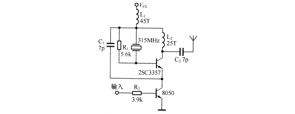
(3) Transmit/Receive Module
The circuit of the DF data transmitting module is shown in Figure 5. The frequency of the transmitter module is 315MHz. When the ambient temperature is -25 to +85 °C, the frequency drift is only 3 x 10⁻⁶/°C. The operating voltage of the transmitter circuit is 3 to 12V. When the emission voltage is 3V, the transmission distance in the open space is 20-50m; when the voltage is 5V, the transmission distance is 100-200m; when the voltage is 9v, the transmission distance is 300-500m; when the voltage is 12V When the transmission distance reaches 700 ~ 800rn, the emission current at this time is 60mA, and the emission power is 500mW.
The DF data transmitting module adopts ASk modulation to reduce power consumption. When the data signal stops, the transmit current drops to zero. In order to ensure the normal operation of the transmitting module, the data signal and the input terminal of the module should be coupled with resistance instead of capacitance.
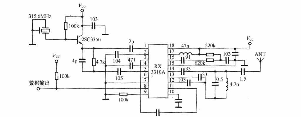
The receiving module circuit is shown in Figure 6. This superheterodyne receiver module adopts RX33 10A wireless remote control and data transmission ASIC and 316.8MHz PfJ F surface wave resonator. The superheterodyne receiver has high requirements on the impedance matching of the antenna, and the impedance of the external antenna